In this article we will analyze a component that was banned until last season. Going forward teams can use variable intake trumpets, also known as croissants intake variable height.
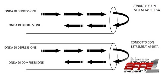
Before you understand what they are and how they work, we will describe the phenomenon on which they are based, the waves and their movement. Without dwelling at this stage as to which is the origin of the wave let us say that they are in general the pressure waves in particular, we can schematize two types of waves: compression wave and depression wave, both can move in a medium which in our the case will be the air and follow a path that is a conduit which in our case will be the intake trumpet. The first one, compression, is responsible for an increase in the local pressure in the area where it is passing, whereas the latter cause a decrease in pressure. When a wave reaches the end of a duct it will be reflected and then return back. On the other end however, the reflected wave may be of the same type or the reverse, in particular if the duct will have an open end of the wave will be reflected with the opposite sign, if the duct has the closed end will be the wave will be reflected with the same sign. For example, a wave of depression that arrives at the open end of a conduit will be reflected with opposite sign or become a compression wave.
We can treat the ducts as open or closed conduits or respectively divergent and convergent. The last definition that it should be underlined before continuing is that of the filling coefficient: ie the ratio between the mass of air actually introduced into the cylinder and that which theoretically could fill a volume equal to the cylinder capacity. This ratio will be greater than 1 in the case where enters an amount of air greater than that which the cylinder may contain, less than one if the incoming air is lower than that the cylinder can hold. In general, the more air that enters, the more fuel can be injected, increasing the engine power. But as we will also see the pair is dependent on this parameter.
After this brief introduction we continue our analysis of the system. We start by saying that the ‘wave’ is formed when we open the inlet valve; due to the recall of air inside the cylinder will be of such a wave of depression. It will move along the trumpet with suction which has a divergent form, up to the end, where according to the theory explained before, it will change sign or will become a wave of compression and will begin to move towards the suction valve. If it fails to arrive to the intake valve before it closes, it would exploit the increase of pressure that the wave generates and would increase in the filling coefficient of that unit value. It is important that the wave arrival in the vicinity of the valve when it is still open and is about to close. Otherwise always we are according to the theory explained before where we could have a series of reflections between a closed end of the conduit and an open end that could lead in the vicinity of the valve at the time of reopening a wave of depression that implies a decrease in the load factor. The task of designers then is to calculate the optimal length of the trumpet valve’s suction so that you will be able to have a compression wave with the valve open and therefore
optimal filling. Unfortunately, this phenomenon is strongly influenced by the rate of rotation of the engine, in fact the time when the intake valve is open decreases with increasing engine rpm. This means that the wave must arrive before in the vicinity of the valve to obtain the benefits on the fill. Obviously the only parameter on which you can work is the length of the duct or of the intake to be shorter. It seems clear that you choose one or the other solution depending on whether you want to maximize coverage at low or at high revs. For motorsports in general it is convenient to have an optimum filling at high rpm. An alternative solution, however, already has been tested in 90 years on F1 engines is that of the variable geometry of trumpet values or the height of which vary in order to maximize coverage at each speed of rotation. In particular, they will be longer at low engine speeds and shorter at high revs. With the video that you will find below you can also figure out how to achieve such resolution. Thanks to the concentric tubes of different sizes inserted one inside the other. With the aid of a scooter outer manages to translate these tubes increasing or decreasing the final length of the trumpet valves.
All this leads as we pointed out earlier to a better filling of the cylinder, but what does it mean? Without going into more technical explanations, we can say that the torque curve follows that of the load factor. Optimizing this parameter at various engine speeds means optimizing the couple, and all that it entails in terms of delivery and driveability. A single critical that we feel we can move towards the choice of this technology is that maybe of little use in the case of turbocharged engines such as those of the current F1. In fact in these engines the filling coefficient is already significantly higher at 1 and the torque and strongly dependent on the supercharging. Obviously we are not saying that it is completely useless since in any case leads to an improvement also in this case, especially at low engine speeds where supercharging is felt less, but certainly you could invest in a different technology
For the record, we note that there was the Renault despite strong opposition from Ferrari and Mercedes to want this solution perhaps because already tested and quick to use, for bridge more easily the gap especially against the Germans. And again for the record, we point out that the only engine manufacturer that has not yet used this technology in existing power unit is the Ferrari, which may usher in the next updates.
Article by
Dot. Ing. Salvatore Di Nuzzo
Translation by Christopher M. Uhl
Scrivi
Devi essere loggatoper commentare.