F1 NOSE 2015 – FRONTAL ANTI-CRASH STRUCTURE

I put a screen example with regard to the computational analysis of the two aerodynamic profiles to get an idea of what it means to CFD, so that you can know what I see every time I hear of it.
It sets the temperature, pressure, flow velocity, the volume control and the profile in order to obtain a kind of diagram of velocity around it. The program is then able to generate a FINAL REPORT which describes the various factors and data involved.
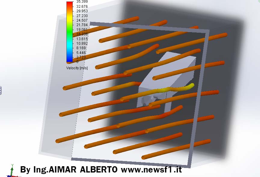
The lines represent the current while the color change is the change in speed.
Note: I take this opportunity to point out a concept on which I always hold throughout the year. You can see that the bottom part being an area that increases the passage section between the surface and asphalt, we see the flow becomes yellow and then slows down from 30 to 27m / sec. As always said, this implies an increase of pressure, which is negative because it reduces the downforce of the car.
Note one more thing: as I set vehicle speed by analyzing 30 m / sec which is about 110kmh.
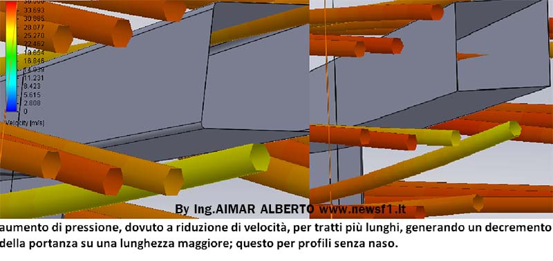
Now we see the analysis of the profile desired by the FIA (without the nose).
Also for this flow I set a speed of 110kmh which corresponds to approximately 30m / sec. The same effect seen and described in the previous profile, with regard to the lower zone is highlighted also in this type of shape with the difference that the pressure increases before (disadvantage).
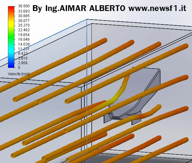
The result is, for the first profile:
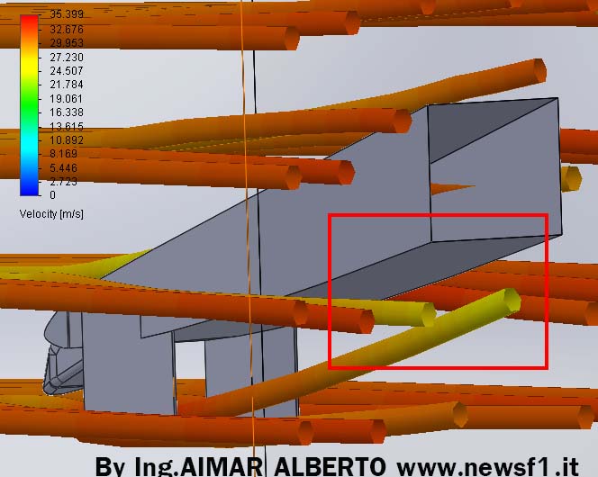
I only want to insert a more qualitative analysis of the speed change that competes to the flow to overcome the obstacle of the profile, as regards both cases, so as to make a comparison from the point of view of resistance of the form of the two types.
I put two pictures side by side at the bottom of which the first is the one on your profile without nose while the top one is the one on the profile with the prominence that we learned about in this year.
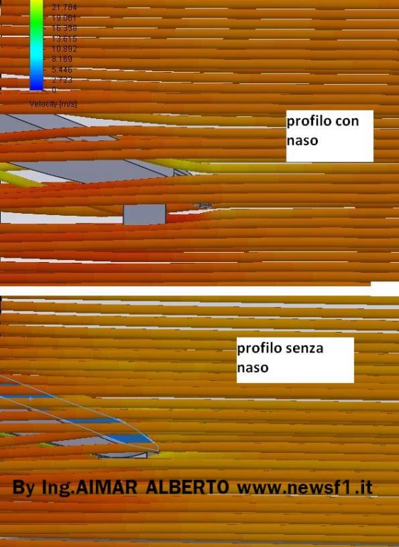
The very first analysis seems that for the desired profile by the FIA could be greater flow stability, given by the shapes of the most delicate profile that distort the air more “slowly”.
Although these two profiles both have advantages and disadvantages, the fact of having used the bulge in this year, and the reason why it could still be used by the teams is the greater amount of air to the lower part, which includes the flow that must reach the flat bottom and diffusor.
Clearly this advantageous feature compared to 2014 will be very, very, resized.
HOW TO TELL IF AN ESTIMATE AND ‘RIGHT?
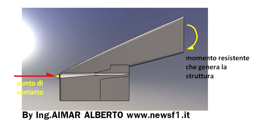
The first thing to do before any aerodynamics that we can do to see if it is beneficial, is the study of the resistant section because then she will have to put up with the first impact in the event of an accident.
There are many ideas online around the sites, but not all may go well (and I speak for those that will be published in the future).
What determines the resistance of a structure? Three main factors:
– The material
– Its layout
– Its shape
The material is almost always carbon fiber, and in this regard I have written a series of articles on AEROSPACE-WORLD at the following link, voice MATERIALS (for those who wish to learn), which will help you to understand how this particular item.
http://aimaralberto.wix.com/aerospace-world#!engineering2/c3d4
Its arrangement is of considerable importance because it will determine, in addition wing maximum force that can support the material, the higher resistance that the component can withstand.
Remember this series of equations:
-M = Moment of resistance (see figure)
-I = Moment of inertia of the section that undergoes the effort.
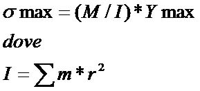
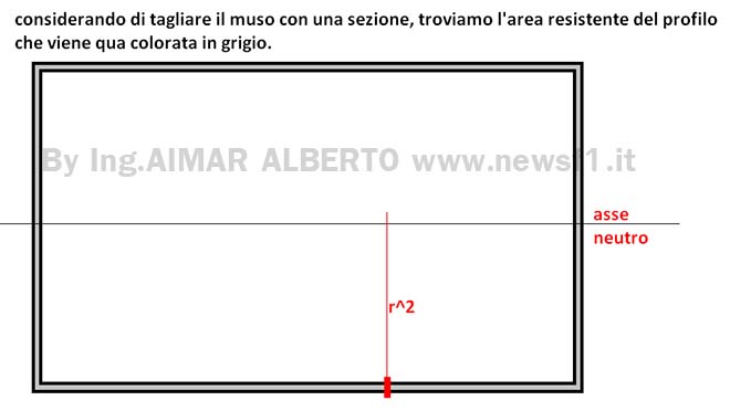
If we notice, in the formula appears that r ^ 2 is the distance of each small quantity of material that makes up the object.
To obtain the maximum stress the M is divided precisely for I, so as to deduce that serves I have the highest possible.
Then we deduce that r ^ 2 has to be very high, we have a section that is large in scale.
This is the first factor that needs to catch the eye to detect when a form may or may not be plausible.
So it would be better not to trust structure that is too thin.
LOTUS STYLE PROFILE
A little side should be open to this type of profile that we decided to call a walrus just a reminder of Williams, who was the first to introduce a similar concept.
There is a paragraph in the regulation that says:
Each section must identify a single area. This is the first implication that erases the possibility of a structure of the type seen on the Lotus to date. I have still allowed to search the hair in the egg, since for grammatical reasons this paragraph may be misinterpreted, but the section of 9000mm ^ 2 and its width reduced in fact prevents a good exploitation of this type of form, so as to make very difficult a solution of this type.
Still remember, though, that I do not want to make predictions, since each technical team has reasons in its own way and teams have definitely given me more to choose various configurations.
What you have read is a starting point and is supposed to be an understanding between all the rumors that are told. Take it as a baseline to understand, of all the things you read, what might be real and what is not! See you soon!
Written BYING. AIMAR ALBERTO WEB SITE :
AIMARALBERTO.WIX.COM/AEROSPACE-WORLD
Translation by Christopher M. Uhl – Twitter