F1 NEWS – UPDATES TO FERRARI REAR WING 2015

The wing that Ferrari brought to Austin for the Grand Prix of America has many interesting features.
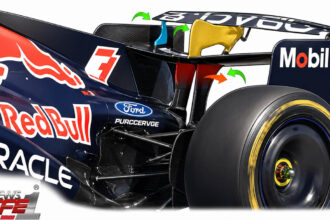
The first of all is a feature that alternates now by several GP and related support vertical reinforcement. In the next picture we see the configuration with a single pylon ran in America then the Russian race with two. (Red Arrow).

Clearly this brings less aerodynamic resistance, just for the fact that the air colliding with an additional element, thus creating not a variation of quantity of motion, and does not create friction effects around its surface, it also has a dissipative phenomena.
The second notable feature is the actuator on the trailing edge (Photo with central circle) that serves to stop the flow causing a bump in airflow and stopping it. The consequence is having a high compression on the upper surface of the wing. This results in a pressure difference between the back and bottom being more conducive to creating downforce.

Among all the precautions, however, one stands out for curiosity and interest, that over all has never yet been seen on the red car this year.
We’re talking about four small air vents, two on each side, which follow the profile of the bottom surface taking air from the outside of the main wing bulkheads, to bring it to flow directly under the airfoil.
In these pictures they are visible on the right side of the car.
Just as he said, it is seen that the two are inclined to each other by a certain angle, and seem to enter the flow from outside to inside right under the curves of the airfoil, and in particular on the surface painted black.
What will never generate these two steps, and why are placed just behind the lower section of the profile, so you can “blow the flow” on the lower wall of the wing?
To understand all this is a theoretical explanation, so you can understand what happens at this point of the car.
You will already be accustomed to hear me speak of Bernoulli and his theorem on the pressure and the velocity of a fluid, but I still have to take it back because it is very important in Formula 1 and in any event is for those who follow us recently:
The law that describes the flow along a current line, and that binds a particular size, the TOTAL PRESSURE, at its two main components that are static pressure and dynamic pressure of the flow is the following:

(within certain limits, beyond which serve corrections)
Where precisely we have Po = total pressure; Ps = static pressure;
The first term, where the speed squared is instead called dynamic pressure; The total pressure is a quantity that depends on the flow and thus by the conditions of the atmosphere, or the place where we perform the test (for example, wind tunnel).
We can modify this element, at least for the greater part of the cases.
The static pressure is the pressure that the fluid possesses. For example, those that can be heard on the ears while you are cycling, if we really wanted to reduce the problem to a minimum. The dynamic pressure competes at the speed.
We note a phenomenon: the dynamic pressure over the static give the total pressure, but we have said that the total pressure does not depend on us: is given of where we are and it is constant over time.
This means that more speeded up a flow, the greater the dynamic pressure, but this leads to a decrease of the static pressure (pedal more quickly and more on your ears will act a lower pressure).
This is the trick: accelerating the flow in order to give lower static pressure (which is that which acts on the profile).
How can you do this? For example, with a convergent duct, or with a passage section which narrows more and more.
By the law of conservation of mass (nothing is created nor destroyed, Einstein would say) we obtain that if the amount of molecules must be equal between input and output, then when you come out of a passage narrower, will only get faster.
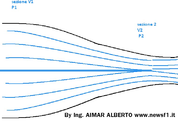
Here so that we get P2 <P1 because V2 <V1.
Returning to our problem, it could be that with this kind in Ferrari have tried to emulate a section duct convergent?
Moreover, if we saw from above the wing could be that the scheme takes precisely the form shown in the following image:
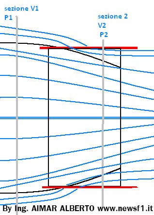
At this point, in correspondence of the lower surface have the restriction of a virtual conduit within which flows our flow, which sees its passage area shrink more and more to have a greater speed.
Written BY ING. AIMAR ALBERTO WEB SITE :
AIMARALBERTO.WIX.COM/AEROSPACE-WORLD
Translation by Christopher M. Uhl – Twitter